
Joule Thief

Power a flashlight with “Dead” Batteries
A Joule Thief is a small and simple circuit that you can build that will let you power a LED flashlight with batteries that you consider “dead”.
Here’s how it does it.
Batteries that you throw away still have power in them, but most battery-powered devices only operate in a small Voltage Range. Because batteries only supply a steady amount of voltage for a little while, devices stop working before the battery is fully out of power.
I won’t try to explain how voltage works here, because you may already know, and if you don’t, I don’t know that I could give the ‘correct’ explanation.
The basics of what this circuit does is take electricity that is higher amperage and lower voltage and makes it so that it can be used to power a Light Emitting Diode, by reducing the amperage and raising the voltage — but it is more fun to build it, wonder at it, and then learn about how it works. Let’s get started.
The name suggests the notion that the circuit is stealing energy — a Joule is unit of energy — from the battery. The term is a pun on the expression “jewel thief”, one who steals jewelry or gemstones.
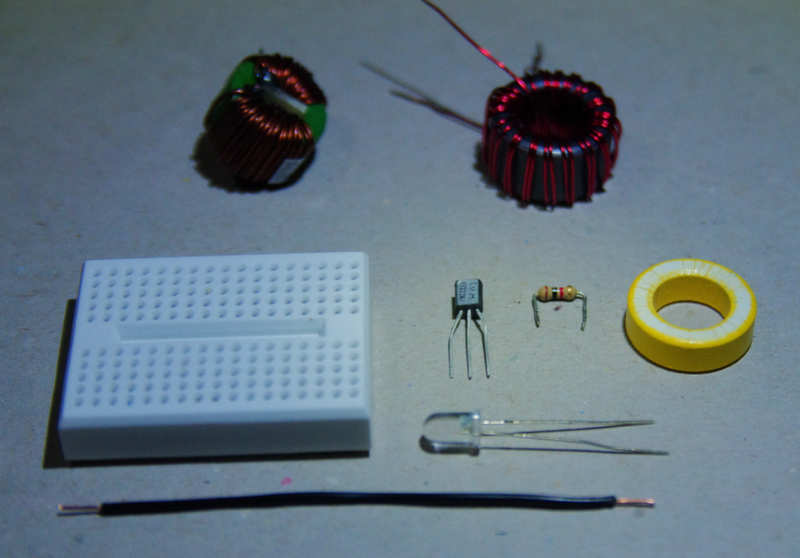
Parts List
First, you will need to have the bits. The nice thing about this project is everything can be salvaged from recycled electronics. All the parts are also easily available online, and at many DIY stores like Radioshack. You will need:
-
A TRANSISTOR: This needs to be a “NPN Signal Transistor”. The following types have been confirmed to work with this project: 2N3904 (very common), PN2222A, and C1815. Whatever kind you choose, and whether you buy or salvage it, make sure you know the ‘Pinout’. The pins will be labeled E (for Emitter), B (for Base), and C (for Collector) — for the rest of this tutorial we will be working with the 2N3904, which has a pinout, left to right, of EBC when looked at from the front (flat) side.
-
A 1k (1,000) Ω RESISTOR: Resistors are measured in Ohms (Ω), and the one we need has a resistance of 1,000 Ohms, abbreviated 1kΩ. Resistors are not labeled with a value, but instead have colour codes: a 1kΩ resistor will have colour bands Brown–Black–Red with another band slightly farther away, which will most likely be gold. You can learn to read resistor colour codes on Wikipedia
-
A LIGHT EMITTING DIODE (LED): These come in all shapes and sizes, and it is up to you what colour and size you use as long as it works. A common type is shown in the parts photo, and has a 5mm body. These are often red or white. Keep in mind that LEDs are Polarity sensitive, so get it the right way around when you build the circuit
-
A “FERRITE TOROID”: This is a small blob of ground up iron held together with glue. When you wrap a bunch of wire around it in a special way that I’ll describe later, it does funny things to the electricity in the wire and makes our circuit work.You can order one online or at radio shack, or salvage one out of a dead electronic device.
-
“MAGNET WIRE”: This is the name for thin copper wire that is coated in varnish. Magnet wire is used in motors, transformers, and other electronic gadgets. It can easily be salvaged from old transformers. You can also get it online or from radio shack. You only need a little bit of it for this project — about 6 feet
-
A DEAD BATTERY (OR TWO): A single AA that you have used a bit should work well for the circuit. If you have a multimeter, you can test your battery: if its voltage is between .8 of a volt and 2 volts, it should work. You may want a holder for it, but that’s optional.
-
A “SOLDERLESS BREADBOARD”: Breadboards are made of plastic and have terminals inside them, so you just insert the wires into the little holes the breadboard, and they will connect to other wires inserted into the same Row. Because breadboards don’t require soldering, they’re reusable. This makes it easy to use for creating temporary prototypes and experimenting with circuit design.
Build the Circuit
How Breadboards Work
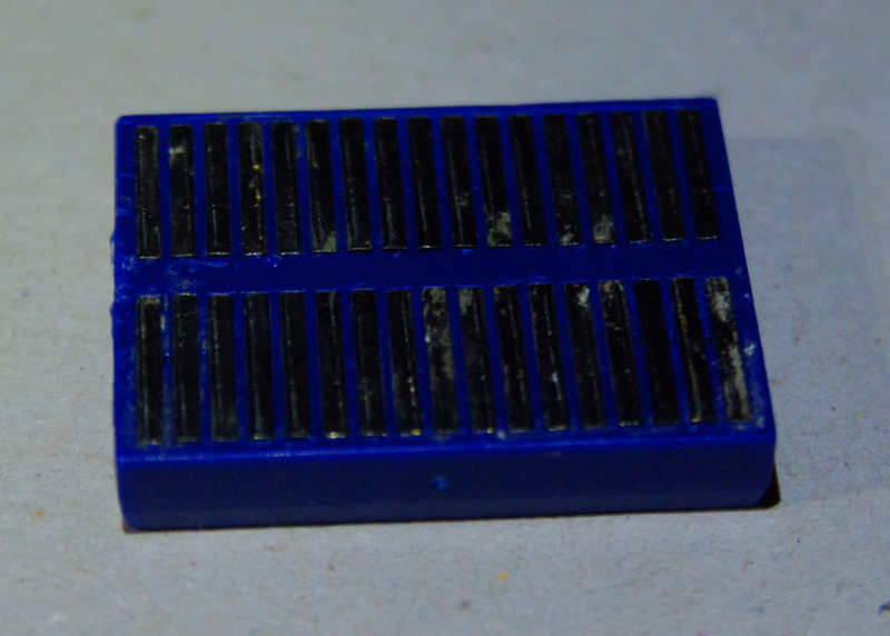
Above is a photo of the back side of a small breadboard. As you can see, rows of metal run out from the centre. On the other side there are holes to insert wires or component leads. When a wire is inserted, it comes in contact with the metal row and becomes connected to anything inserted into the same row. On larger breadboards, there are often “Bus” strips, which run along the edges, separately and in the opposite direction. Keep this in mind if you are using a larger breadboard.
The Transistor
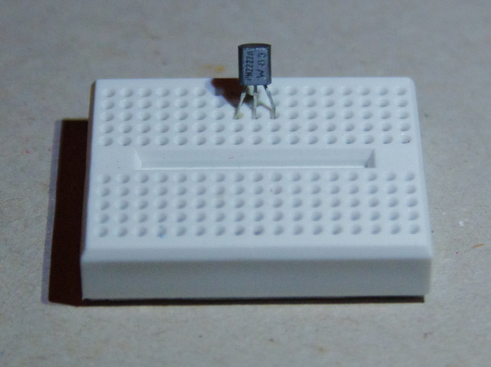
Pop the transistor in as shown, with each lead inserted into a separate row of the breadboard.
The Resistor
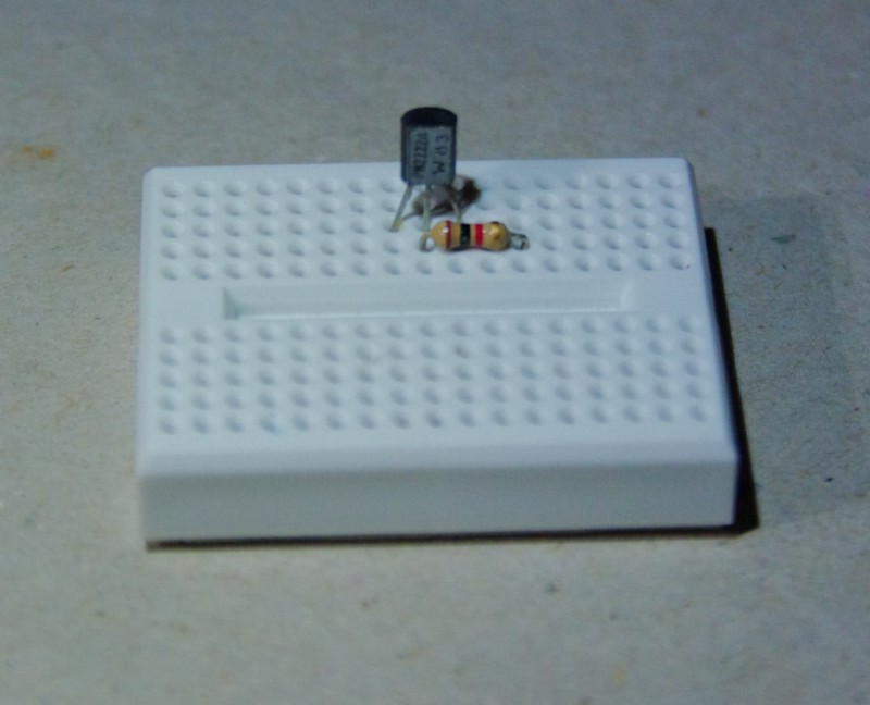
Add the resistor so that one of its leads goes in the same row as the transistor’s Base (the centre lead for 2N2222A and 2N3904 transistors, such as the one shown). The other lead of the resistor can go into the row two to the right of the transistor’s Collector, as shown.
The LED
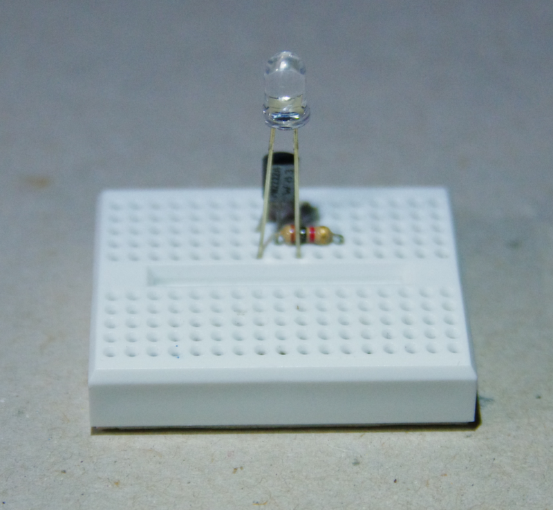
Add the LED so that the Negative (-) lead goes in the same row as the transistor’s Emitter (if you use a 2N3904 or PN2222A, this is the left lead), and the Positive (+) lead goes in the same row as the transistor’s Collector (if you use a 2N3904 or PN2222A, this is the right lead).
You can tell which is the positive lead of an LED because the part it’s attached to inside is smaller. If it is a new LED that you bought, the negative side of the lens will have a flat spot, and the positive lead will be longer. You can test an LED easily with a 3 volt battery to check its polarity.
Winding the Coil
The coil ‘winds up’ being the most critical component in this circuit. Here’s how to wind it:
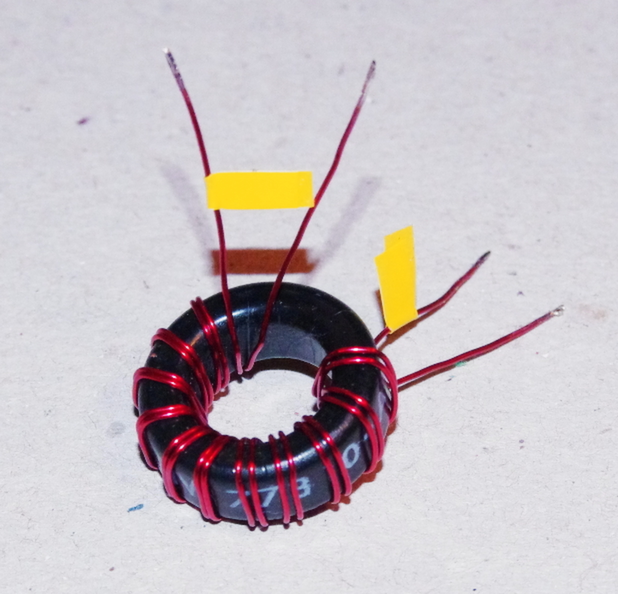
- Take a generous amount of Magnet Wire — around six feet, depending on the size of your Toroid — and cut it into two equal lengths. You can also just fold it over on itself for the winding, and cut it when you are done.
- Hold the two wires side by side and pass them through the Toroid, so that they form a full turn around the toroid, and are next to each other. It is important that they NEVER CROSS. Draw them tight.
- Repeat until you have 11 to 17 wraps with each wire. Make sure you keep them tight and make sure they never cross, and that you keep them as a pair (as shown).
- When you are done, you need to remove the varnish from the four wire ends so that you can connect them to other components. This can be done by burning it off with a lighter, sanding it off, or scraping it off with a knife. Sanding is the most civilized option.
- In the photo above I have flagged one wire with tape at each end. It is important to know which wire is which when you are done. This is easily done with an Ohm-meter (check which of the four wire ends are connected to each other), but it can also be done by staring at it long enough.
- Take the two ends that are not the same wire and are also not from the same end of the coil, and twist them together. This forms the Center-tap of the coil.
The Coil
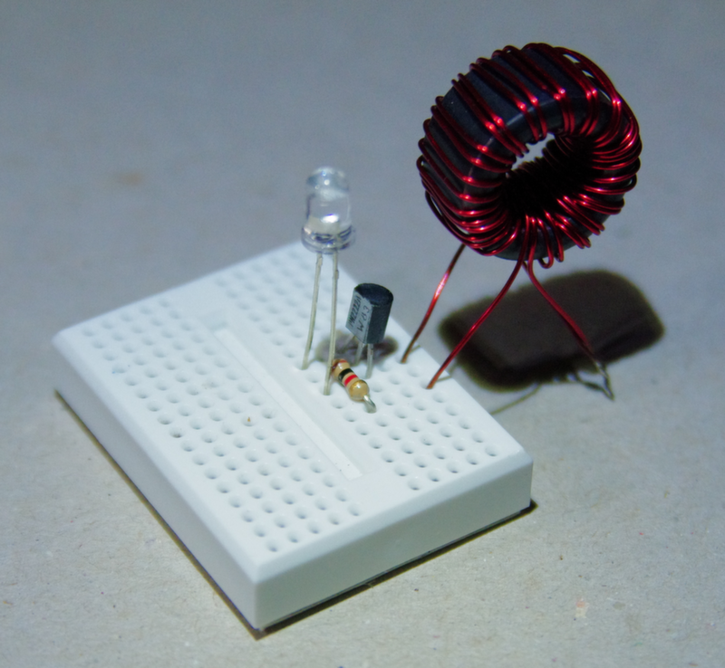
Insert the single coil leads into the breadboard, one in the row with the transistor’s Collector and the LEDs positive terminal, and one into the row with the transistor’s Emitter and the LEDs negative terminal.
The Wire
Insert a short length of solid-core wire into the same row as the transistor’s Emitter. This is your negative power lead.
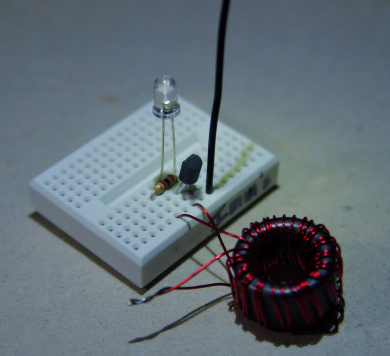
See if it Works
You’re done ... hopefully. Let’s test the circuit.
Take one last check to make sure everything is wired correctly (check the polarity of the LED & transistor!), and make sure you got the windings on the Toroid right.
If everything seems A-OK, touch the negative power wire (which should be black) to the negative terminal of the battery and the positive power wire (the Center Tap of the Toroid) to the positive terminal of the battery.
Lights? Camera? Action? If the LED lit up and you let out a shout of victory, you are done!
One small note: Depending on how fresh the battery or batteries are, it is possible for the circuit to make too much power for the LED. If the LED is bright when you first turn it on, and then dims — particularly if it also changes colour — it is likely getting too much power. In this case you should replace the LED and try again with a weaker power source.
A Technical Digression

So now you have this neat circuit that you built with your own two hands, and chances are you don’t have a clue how it actually works.
Courtesy of Wikipedia article:
The circuit uses the self-oscillating properties of the blocking oscillator, to form an unregulated voltage boost converter. As with all power conversion technology, no energy is actually created by the circuit (in accordance with the law of conservation of energy). Instead, the output voltage is increased at the expense of higher current draw on the input. As a result, the amount of power entering the circuit is the same as the amount leaving, plus the losses in the conversion process. 1
Here are some places where you can learn how the circuit actually works: